Augmented Reality is more than Virtual Reality
Towards Wearable,
High-Performance
Augmented Reality Displays
High-Performance
Augmented Reality Displays
All rights preserved. Patents pending1 on approaches presented in this paper.
Download PDF version
Note: Supplemental materials, the Blender model used for the simulations, and a set of video tutorials can be obtained (for non-profit use only) from the website of the book "Displays - Fundamentals and Applications, 2nd edition" (see "material" page), or just here from this page.
Abstract
A novel optical configuration for an augmented reality (AR) display and optics is introduced, consisting of a curved, transparent display and a curved mirror. The image is seen through the back side of the transparent display, whose image is reflected and focused towards the users eye by the mirror.
It is demonstrated that this configuration delivers not only a very large field of view and high resolution but also, contrary to what one would normally expect, a very large eyebox.
It is shown that this approach will allow for high performance AR displays hardly any bigger or heavier than a pair of normal, light-weight, state-of-the-art prescription glasses, that can be worn using the same convenient type of frame, due to their light weight and large eyebox
First a more conventional design is analyzed, using only a curved display and one mirror in an off-axis configuration. An ideal optical design for this, using ellipsoid shapes, is presented. The analysis reveals that just the configuration being off-axis inhibits any better performance. By introducing a transparent display, a coaxial (“on-axis”) configuration with spherical displays and mirrors is enabled, yielding a virtually unlimited field of view (FOV).
Furthermore, an iterative synthesis method for mirror shapes is shown, and applied to the synthesis of mirrors for coaxial configurations with planar or cylindrical displays, also yielding results better than with most conventional approaches. The designs are analyzed by high precision 3d raytracing, allowing to simulate not only the optical performance but also their physical appearance.
Introduction
Current augmented reality (AR) displays usually are bulky and need of special fixtures to the head, not only because of their weight but often also because of small eyeboxes (the range in which the eye can move without losing too much resolution, or even optical contact). Also the FOVs (fields of view) normally are quite narrow. Smaller, eyeglass-like models so far have been data displays with even smaller FOVs.
The most promising approach up until now have been waveguide displays. Simple ‘glass slabs’ generating images seem quite elegant at a first glance. For a good resolution, however they need to be about 2 mm thick, and usually three are needed, one for each base color. Another disadvantage is the FOV of typically 40° or less.
A common assumption so far has been that with near-eye displays, providing an image to a user by means of conventional optical elements will either result in a very small field of view or will require very complex and bulky assemblies (e.g., [6])..
The concept presented here1, in turn, provides for compact, light-weight AR glasses hardly bigger and not heavier than the most advanced prescription eyeglasses, and this with a very large FOV and a large eyebox, making them just as wearable and acceptable for everybody. The approach requires transparent and - in most of the variants - flexible displays, but such are achievable and examples have been presented since years.
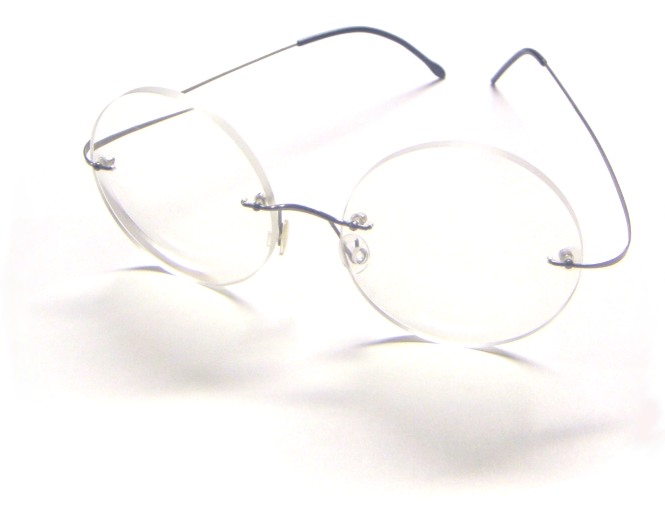
Fig. 1 shows a pair of state-of-the-art prescription eyeglasses with high-tech plastics lenses and a titanium frame. The entire assembly weighs just 11 g.
Fig. 2 compares this to one of the novel AR display assemblies proposed, including an integrated prescription lens. It is almost as compact and may even be lighter than the eyeglasses, and it has a large eyebox, so the same, convenient type of frame can be used.
Even this very simple, flat display assembly offers a FOV of 40° at good resolution and a lot more beyond that. Introducing just a slight display curvature improves FOV and resolution figures significantly. The ideal optics assembly uses spherical display and mirror shapes, yielding virtually unlimited FOV and resolution, while maintaining the large eyebox. The best configuration may lie somewhere in between, depending on application requirements.
Fig. 3 shows a photographic rendering of the flat and spherical display variants.Fig. 1: An example of conventional state-of-the-art prescription glasses. Total weight: 11g.
The AR display concept proposed here aims at providing full fledged AR glasses
just as light and convenient, with large FOV and high display performance.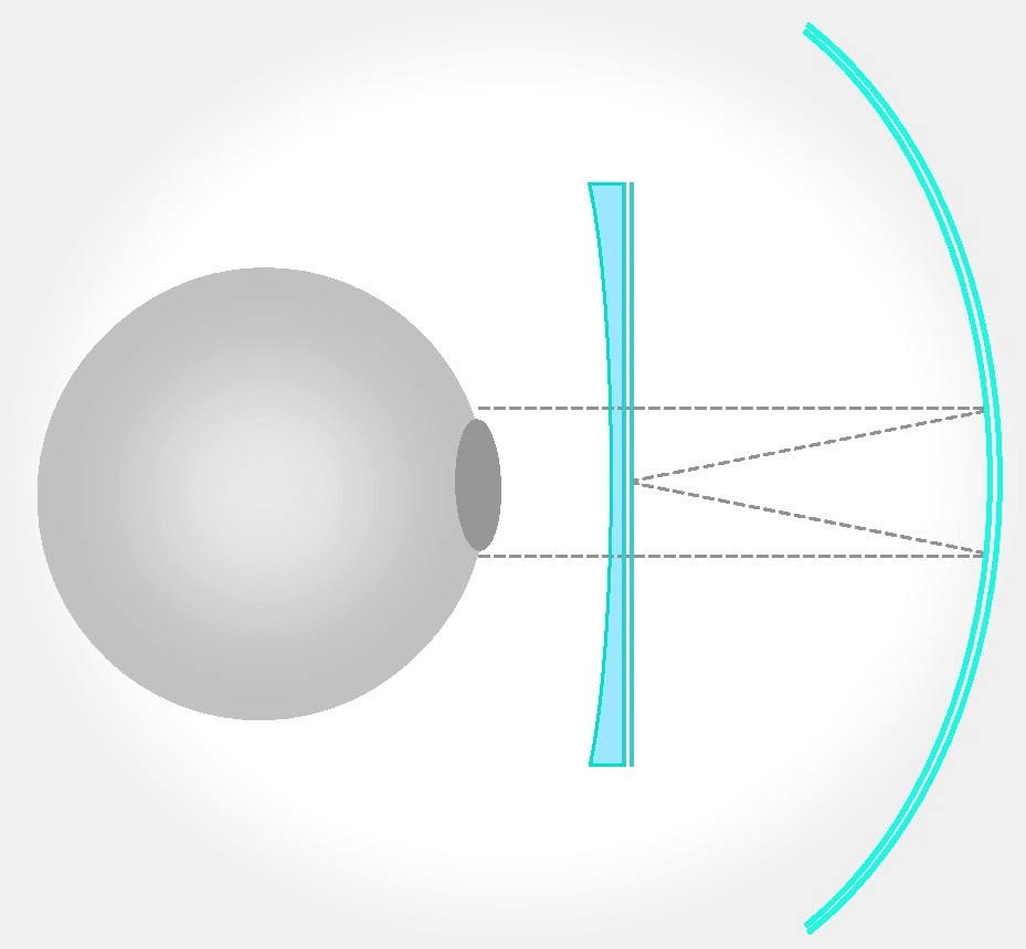 Fig. 2: Left: the flat display variant proposed, including an optical prescription lens.
Right: the state-of-the-art prescription eyeglasses assembly of Fig.1 (lens diameter is 50 mm).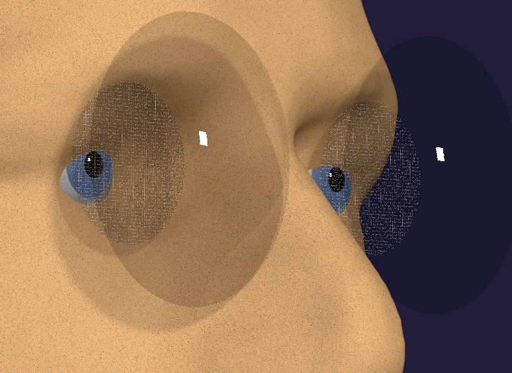 Fig. 3: Left: flat display and dome mirror, hardly bigger than conventional eyeglasses.
It could still be reduced in the upper part (over the eyebrows), without affecting the FOV.
Right: spherical displays and mirrors, yielding ultimate performance, yet a bit bigger.
The best configuration may lie somewhere in between, depending on application requirements.
.
A look at conventional designs
Near-eye displays have some functional requirements different from other optics designs. A very important fact results from the limited crisp perception area of the human eye, in conjunction with the large angular range required for a versatile near-eye display (NED). A crisp image of a scene can only be acquired cognitively in the brain, by relentless eye movements from detail to detail. To illustrate the consequences for a near-eye display, we regard a simple, single-mirror design as shown in Fig. 5. When a user points his eye towards any particular area on the display, only a tiny fraction of the mirror is involved in the image formation for that particular point. This also differs substantially from classical optics designs in that the real exit pupil of the collimated system is in the center of the eyeball, not in front of the eye pupil.
Fig. 1: Principle of point formation for NED
In a collimated configuration, i.e. with the virtual image at infinity, the mirror section involved has a diameter of 2 mm for the maximum eye resolution of 1 arcmin. This is simply the pupil size corresponding to this resolution, projected onto the mirror. A smaller pupil causes lower resolution due to beam shaping constraints, a larger pupil also tends to lower resolution, because of aberration. Any of the small mirror elements effective for different angles can therefore be optimized for the particular incident beam angle on the mirror, and the focus distance to the corresponding point on the display.
The ideal shape for any such limited area on the mirror would be a properly chosen section of a properly chosen paraboloid. Then we should get an ideally crisp focus point. Alas, the curvature of the entire mirror is not simply the sum of small paraboloids, nor is it a paraboloid itself. We have to find a compromise between the local and the general shape.
The general shape of the mirror would have to be optimized to have all focus points on the display plane, while retaining the best possible approximation to the aforementioned paraboloid shape for any single pupil sized region on the mirror. The concept may work a lot better with a display having a convex shape itself, as has already been indicated in [1] and [8].
One of the first explorations, concerning the performance of single mirror approaches as in Fig.5, has been carried out In [2]. It included designs with a naked flat display and with a flat display with a thin correction lens. The angular resolution achieved was about 1.5 arcmin for a design including a lens. For the design without a lens, an explicit number was not given but from the contrast curves it appears to be about 3 arcmin. The fields of view (FOV) provided were about ±10° (20° total).
This is about what could so far be expected with planar displays. Some modest improvement may be gained if image distortion is taken care of by pre-compensation in the display image, which has meanwhile become common and efficient method with electronic cameras.
Not that in this paper, we therefore ignore any kind of image distortion, in favor of maximum resolution and field of view. Also note that the displays may need a dynamic distortion compensation, taking care of the eyeball rotation.
In military display helmets, large stacks of about a dozen lenses are typically used to prepare the display image. Such stacks are usually placed sideways from the head, and the size and weight of the assembly render it impossible for most non-professional applications (see [3], for an example; the approach expands the principle with two very large ellipsoidal mirrors and a lot of lenses, yielding an extremely wide field of view, but at the expense of an even bigger assembly).
Resolution Requirements for AR Glasses
At this point, we should take a look at the requirements for display resolution. Fig. 4 shows an average person’s eye resolution as it decreases from the center of view. At the very center, persons with good eyesight resolve up to 1 arcmin. This is the target figure for perfect displays. Please note that in practice, lower resolutions may also be perceived as crisp, if detail contrast is high. Up to 2 arcmin. of resolution, an image may therefore be perceived as perfectly crisp. Moreover, the maximum resolution needs to be delivered only for the very point the eye is currently looking at. From there, it can be allowed to decline according to Fig. 4. The optical design only has to provide that the crisp area follows the eye rotation.
For the outer ranges of very wide fields of view, even lower requirements apply, as the human eye can only rotate up to a certain limit. The rotation limit is approx. ±45° horizontal and vertical. Hence, outside of an approx. 45° range (90° FOV), we may therefore allow for a decreasing display resolution or a degrading optical quality, or both. This is far out of the FOV range of most current AR displays, but for the solutions presented here it may become an aspect to consider.Fig. 4: Eye resolution vs. angle from center [1].
Introducing curved displays
The first new design we regard will be the off-axis configuration as in Fig. 6. A problem here is that a spherical mirror would show a severe astigmatism when used at an angle. A way to avoid this is a an ellipsoidal mirror. Moreover, regarding the above statement “the real exit pupil of the collimated system is in the center of the eyeball, not in front of the eye pupil”, we take the eye center as one focal point of the mirror ellipsoid. Then, all rays from there would converge at the other focal point (Fig. 6).
This is not yet exactly what we want, however: while the eye center is a location where all display rays approximately converge, any particular ray bundle coming from the eye pupil has to be assumed parallel, not converging (eye accommodation at infinity).
If we regard the pupil sized area of the ellipsoid mirror involved, it will approximately behave like a simple concave mirror or a lens with focus lengths f1 and f2 in the directions of the ellipsoid foci F1 and F2. If we move one of the foci (the one on the eye side) to infinity, the other one gets closer, according to the lens formula f = 1/(1/f1 + 1/f2).
The calculation returns that all focus points on the display side now come to lie on a smaller surface inscribed in the ellipsoid. The surface obtained this way is almost exactly an ellipsoid itself, around the same focus points as the mirror ellipsoid. With different values for the position of F2 and the mirror radius, we have four discrete parameters for further optimization.
Fig. 6: Left: an ellipsoidal mirror yields the best point formation for off-center configurations.
Right: if the beam is parallel on one side, a focus of length f2 results on the other side
Although this appears to be a geometrically elegant result, we cannot simply expect it to be perfect, because the simple focus distance calculation is correct for the respective center rays at any eye rotation only, hence the peripheral rays do not perfectly converge in the focus point, and the aberration appears to be more of a problem with off-axis designs.
The results obtained, however, are already far better than examples known from planar displays, proving the viability of the concept of curved displays.
If the shapes obtained here could be considerably improved by a further optimization, the general synthesis algorithm proposed below this paper could be a tool to explore this. On the other hand, the ellipsoids shown may also be quite ideal, as we can see them as derived from the ideal spherical design we will show below, by a simple coordinate transform. Hence at least, the shorter the ellipsoid, the closer it should be to the ideal shape.
Aberration with the off-axis configuration
It is commonly assumed that the spherical aberration of a pupil sized lens or mirror with a focus length equal to that of the eye pupil will cause about the same spherical aberration and should therefore the system resolution should not turn out lower that that of the eye.
One might expect this to hold for off-center designs with ellipsoidal mirrors as well. The ellipsoidal design however results in a considerable radius and hence focus length change (aberration) from one end of the mirror surface element involved in the point formation to the other (r1 to r2, Fig. 7). We will see the results of this in the optical simulation.Fig. 7: Even though only a small area a is involved in the formation of an image point,
the mirror radius changes, from r1 to r2 in this example.
Optical Simulation
We will now regard the optical quality of the approach. As stated before, we do not consider image distortion, because it can be compensated electronically. What has to be evaluated, is the amount of aberration and astigmatism introduced by the mirror elements when being used for a focus length different from the genuine ellipsoid focus.
The designs were evaluated by precision 3D raytracing, using Blender and the Cycles rendering engine. Blender is a full-featured open source 3D modeling, rendering and animation environment. It also allows for an evaluation of the optical performance, at least of mirror designs. While it cannot replace a specialized optical design software in all detail, the resolution and optical appearance of the designs presented here can be explored almost perfectly. CUDA acceleration allows for very fast, almost real-time rendering with current graphics hardware.
Calculated freeform shapes were imported into Blender as vertice lines, by a csv reader plugin. The curves imported then were expanded to 3D shapes by rotating (spinning) them and deleting double vertices when done. Exporting to stl format and re-importing optimizes the surface for rendering. Another very important step is to set 'smooth' rendering for the surface faces.
With these techniques, Blender's camera model delivers accurate optical renderings of displayed image detail to resolutions of 1 arcmin or even below. A ‘camera’ attached to the eye pupil position allows to explore the virtual images in all aspects. We should however note that raytracing simulations generally cannot cover purely wave-optical effects, like blurring by very small camera apertures. But this is not a problem here as long as we keep it in mind.
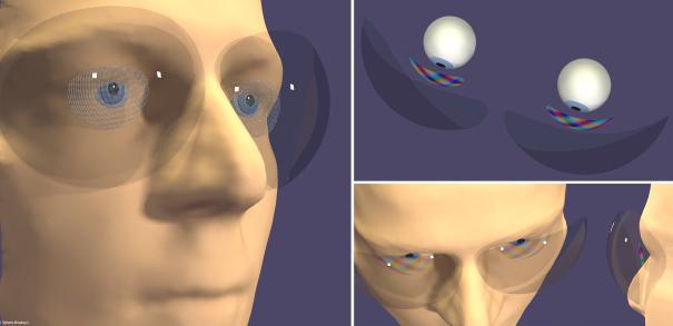
Displays are simulated by luminescent surfaces, with Image or test pattern textures. The nodes surface model of the Cycles engine also allows for unidirectional emission, as well as back side transparency. A special advantage of a full 3D modeling is the capability to include detailed anatomic face shapes, allowing to evaluate the visual appearance of the designs and to detect any physical conflicts with the mirrors or displays.
Simulation results - ellipsoidal display
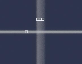
Fig. 8: ellipsoid design of a free-form NED, here cropped to the useful area for maximum vertical FOV. The displays are showing a full area photo. Fig. 9: resolution evaluation. Top left: center. Top right: 20° upward. Bottom left: 20° left. Bottom right: 20° down. The overlaid rectangles are 1arcmin x 1arcmin.
Fig. 8 shows a complete 3D modeling of the ellipsoidal design, including mirror simulation by ray tracing, and an anatomically correct head model. The glasses and display edges are but roughly cut (real glasses would have some nicely designed edge shapes).
The field of view of the ellipsoidal design can be very large in the horizontal, more than 140° total, with a binocular center range of 80°. The vertical range, although limited to about 45° by the display edge getting into sight, is still competitive, regarding existing designs.
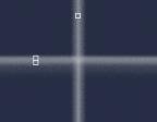
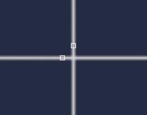
Fig. 9 shows images of a crosshair grid test pattern, with grid lines originally less than 1 arcmin thick.
As expected, the display is almost free of astigmatism and the center of view is the location of best relative focus for any eye rotation angle. We see that the optical resolution partly falls short of the desired 1 arcmin. The vertical blur effect may be attributed to the focus change along the vertical extension of the effective mirror area which is certainly an effect present in off-axis designs. For the horizontal, we see a degradation from about one arcmin at the top to 2 arcmin (full contrast) at the bottom. This may indicate some space for further optimization (we should remember that the ellipse calculation was done by a simple focus law application, and the 2d result has simply been rotated to obtain the 3D shape).
The static peripheral resolution turns out to be more problematic. The simulation yields values only half as good as the peripheral resolution of the eye, or even less, especially if the eye is rotated up or down.
In conclusion, both the center and peripheral resolution of the ellipsoidal off-axis design still do not fully match the human eye resolution. While the results achieved are better than with planar displays and may still be perceived as reasonably crisp in some applications, we will have to think about ways of improvement.
This could be approached by an adaptation of the general mirror construction method we will propose later in this paper. The limited vertical FOV of the ellipsoidal design, as well as aesthetic aspects, could also be approached by this method.
Dynamic focusing according to eye position would add another degree of freedom for the display and mirror shapes. Yet even with all these approaches, the margins for improvement may be limited.
Introducing coaxial (“on-axis”) displays
We have seen that the off-center optics design is problematic in terms of optical quality, size and aesthetic appeal. Avoiding the slanted beam angles should be of advantage.
Consider a display that is transparent from its rear side and emits to the front side only. What appears strange at a first glance, can be indeed be achieved, by inserting transparent areas into a single sided display. These can either be gaps in an otherwise non-transparent display structure, or areas of fully transparent driver circuitry. Only the pixel areas have to be occlusive, to cancel out emissions to the rear. Fully transparent notebook displays have been demonstrated several years ago. A single-sided emitting variety has been demonstrated by Toshiba in 2013 already (dubbed Transmissive Display).
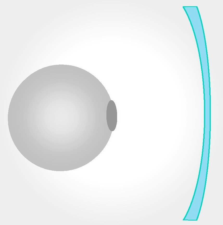
Fig. 10: Left: a spherical mirror yields perfect point formation at its center.
Right: if the incident beam is parallel, a focus of length r/2 results.
Consequently with such a display, we can abandon the off-axis approach. We may use eye-concentric spheres for display and mirror (equivalent to ellipsoids with zero focus point distance). A closer look reveals that there is about one ideal size for these Spheres: 4 cm diameter for the display and 8 cm for the mirror. The focus length of the sphere requires this ratio of 2:1 (Fig. 10), while the distance between left and right eye limits the mirror size, because mirrors too big would collide in the middle (Fig. 11). The display sphere sizes, on the other hand, should be sufficiently bigger than the eyeball, to achieve a comfortable clearance towards the face.
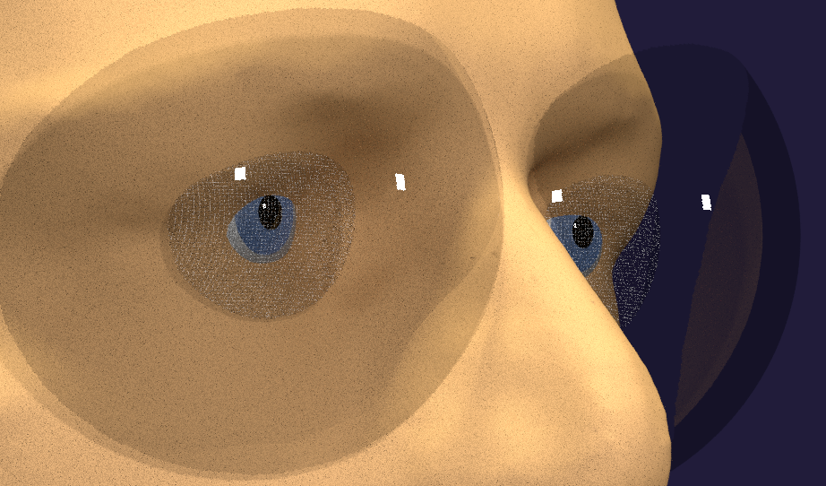
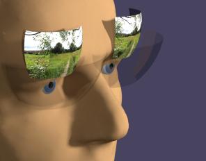
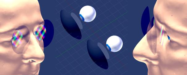
Fig. 11: Photorealistic rendering of spherical glasses. The mirrors are half reflective. The displays in the left image are showing a very thin test grid pattern (with lines <1 arcmin wide).
A complete display design of this type would use only properly chosen sections of the spheres, according to physical limitations by the head shape.
The 3D modeling (Fig. 11) shows that with an ample clearance towards face and eyes, almost the entire visual field can still be covered. It also shows the device to look better and be more compact than the ellipsoidal one considered before. Smaller shapes for the mirrors and displays are possible, and should still deliver a sufficient FOV in many applications. A mechanical frame construction will have to be approached separately, and also the integration of further components (e.g., eye trackers).
An irritating property of this approach could be the brightness of the display: in order to produce an equivalent visual brightness, it needs to be up to 4 times brighter than the environment. This could occlude the eyes of the user and look quite awkward. In augmented reality applications, however, only a few virtual objects will usually be present, and they should normally not be in the direct view ahead, as this would obstruct the sight on the real world in a hazardous way.
A possible measure reducing this effect would be limiting the r, g and b colors emitted and reflected to narrow bands (e.g., using dichroic filters and mirrors), which would increase the effectiveness and the visual transparency of the mirror and greatly reduce any light transmission to the outside.
The regular micro patterns of the display might perhaps lead to diffraction effects, mainly with shallow incident angles. If this would constitute a problem in some cases, introducing some irregularities (dithering) to the display patterns should help.
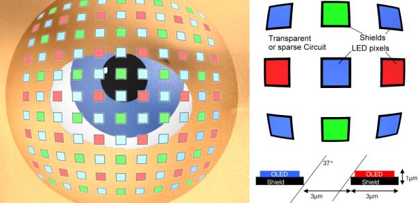
The gap structure of the transparent display would need to be very fine for our application, according to the targeted resolution of 1 arcmin. For the 2 cm display radius conceived, 1 arcmin means a pixel raster of 6 µm. Here we should perhaps start from an entirely transparent design, insert larger gaps between the pixels, and then cover the pixels up from the back side (Fig. 9). This could allow for a high transparency (e.g., 75%) as shown in Fig. 12.
Fig. 12: Illustration of a transparent display matrix on a spherical glass (left, with greatly enlarged pixels). Matrix and layer detail and maximum incident beam angle occurring (right).
Fig. 13: Assessment of the max. possible incident angles on the spherical display
Fig. 13 shows the maximum incident angle from the eye towards the display, which should be taken into account for the layer design. With typical OLED emitting layers only 100...500 nm thin (Fig. 12), this should not be a problem. Typical OLED pixels would themselves be transparent and emit to both sides, and the shields would be implemented as mirrors.
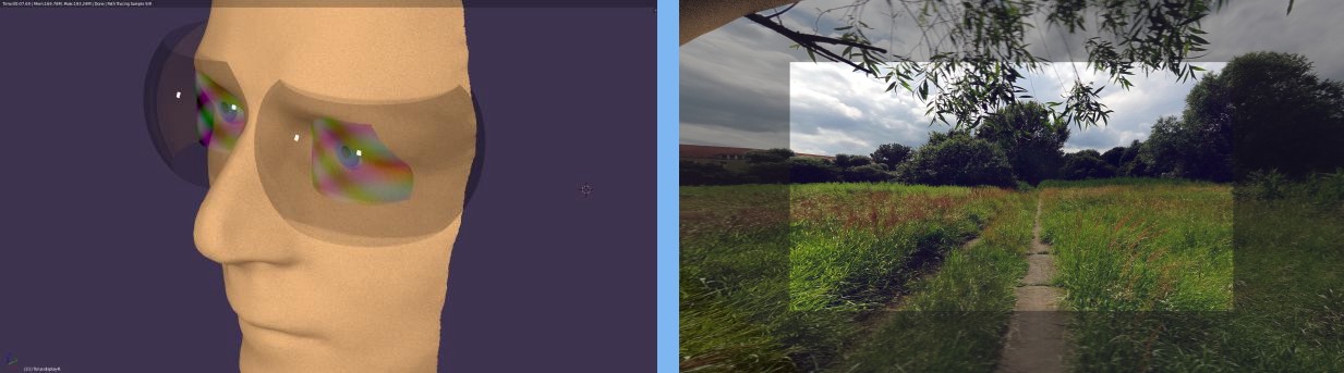
Fig. 14: Display view of a real photo image, right eye,
showing the FOV of a 24 mm equiv. photo lens (appr. 40°x70°).
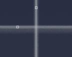
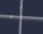
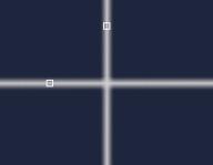
Fig. 15: Beam spread of the coaxial spherical display at center (left) and with the eye camera turned right 20° around the pupil position, assessing the eye peripheral resolution (right). Squares of 1arcmin x 1arcmin are overlaid for comparison. The grid lines displayed are originally <1arcmin wide.
The optical quality of the spherical coaxial optics design proves to be very high, which does not surprise as the only limiting factor here is the spherical aberration of the mirror areas involved. Fig. 15 shows the simulation results. Indeed, we see that the 1 arcmin target is even surpassed for usual contrast transfer figures. This holds for any eye rotation.
The peripheral resolution is 2...6 times better than that of the eye (cf. Fig. 4). Hence, this display type can achieve 100% resolution and a very large FOV.
An effect occuring with this display type is a faint reflection from the user's eye and skin appearing in the mirror. This image appears very blurred and enlarged, with the pupil always following the center of view. Given the dark color of the pupil, contrast values should not be greatly affected. Moreover, monochromatic light sources (quantum dot enhanced phosphors, e.g.) and narrow-banded mirrors would efficiently suppress this effect.
The Eyebox
The Blender model also allows to simulate a shifting of the entire glasses, e.g., when sliding down the user's nose by a few mm, which is a common problem with traditional glasses frames. Results indicate that for a retention of close to optimum crispness, the ellipsoidal assembly will tolerate only about 2 mm, while the coaxial spherical assembly can easily abide 5 mm or more (in one direction, which indicates the total exit pupil is rather about 10 mm). Resolution in this case will only drop from 1 to about 1.5 arcmin, which is hardly perceivable in practical use. Vignetting does not occur.
Note that in [6],a display concept was proposed that at a fist glance has similarities to the designs shown here. However, an adaptive multi-cell holographic mirror was used, assumed to be absolutely necessary. The main problem might have been that a very small eyebox was assumed for any static mirror. Indeed, the large eyebox shown by the simulations presented here came as a big surprise.
A synthesizing method for mirrors for arbitrary display shapes
Fig. 16: Algorithm for incremental mirror synthesis
We will now suggest a straightforward synthesis procedure for mirrors for arbitrary display shapes. It can be used to synthesize entire mirrors, but also to calculate alternative shapes for the edges of otherwise constructed mirrors (such as spherical or ellipsoidal ones).
The underlying idea starts from the fact that the effective beam width for point formation is small (pupil size). Fig. 16 shows the pupil size greatly extended for better illustration. The active mirror section could be approximated, at its edges, by two little planar mirrors (m1, m2). The optical effect of said section, focusing a beam of light, can completely be modeled by the two mirrors, reflecting the edge rays of the beam.
The curve between these mirrors will always be very well approximated by a circle sector (with center point f1), provided the section is chosen to be small enough. The angles of m1, m2 that we choose to start with, are known. The point where they meet on the display (image point p1), is then easily constructed.
Now we rotate the eye by one pupil or beam width. The mirror m2, now at the other edge of the beam, gives us the location of a next image point on the display, p2, and this, in turn, dictates the angle of a next mirror element, m3, at the other side of the pupil beam. The spatial position of that next element (its distance from the eye) can perfectly be determined using the sphere sector shape we expect between the mirrors (with center at f2).
Iterating this method, we get a number of elements approximating a curve, which should turn out to be the ideal mirror shape for that display.
Repeating the entire procedure for eye rotation from the center upwards, we complete the vertical center line of the mirror.
Note that the iteration process may use arbitrary small pupil sizes to improve its resolution and precision.
If we try to combine iteration steps like this steps in the horizontal and vertical, we will most certainly get conflicting values and will have to figure out how to combine them for a suitable result.
For a rotation symmetric mirror, however, we may use the algorithm simply from center to edge, defining a complete mirror shape in a most simple way. This of course has the disadvantage of neglecting the lateral curvature and introducing more astigmatism. We will see this in the following example. Yet, the shape found there nevertheless turned out to be as optimal as possible.
We should note that the principle of the algorithm can also be used to calculate a display shape for a given mirror shape.
Mirror synthesis example: Dome mirror and flat display
As a proof of concept, we show a two-dimensional implementation of the mirror synthesis method. It can already be used in practical designs, involving coaxial and rotation symmetric components, such as dome mirrors in conjunction with transparent planar displays.
Fig.17: principle of the planar display - dome mirror design.
The progressive curvature necessary in the radial directions, needed to keep focus on the planar display, in this case is not accompanied by a similar curvature in the circular directions. This causes growing astigmatism towards the edge.
One may think that a three-dimensional mirror synthesis could avoid this, but it won't really work: we would need stronger z curvature to reduce astigmatism, but this can only be achieved by more progressive xy curvature, again requiring even stronger z curvature. Which proves to be a never ending iteration, rendering the problem unsolvable. Hence, the shape we got is the best possible.
It should be noted that in [5], a similar configuration was postulated, with the assumption that an ideal mirror could be calculated. As we could show, this is not the case. The only way of improving this configuration is a curved display.
Fig. 18: Synthesized freeform mirror example with flat transmissive displays.
Fig. 18 shows the assembly, with two circular flat transparent displays of 29 mm diameter and dome mirrors of 50 mm diameter. This design is not bigger nor heavier than a simple conventional pair of plastics eyeglasses. It allows for an FOV of up to 70° in all directions, but astigmatism remains decent only up to about 40°.
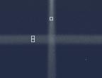
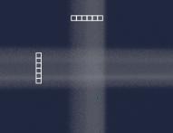
Fig. 19 shows that the center resolution of the design is almost as good as with the coaxial sphere design. At 20° lateral eye rotation, the lateral resolution is still at its optimum, proving the mirror synthesis algorithm to work correctly (this is exactly what it was intended to deliver). The astigmatism, however, is strong, and as argued, this cannot be successfully addressed by changing the mirror shape. What can be done, is adjusting the local focus, for equal y and z blur. There are four ways:
1. Leaving it to the user's eye accommodation, requiring accommodations to, e.g., 1.25 m.
2. Bending the display, (this needs only about ¼ mm for a significant improvement).
3. Using a mirror with a bigger focus length (makes the assembly a bit more bulky).
4. Using an anyway desirable dynamic focus feature (moving the display forth and back).
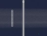
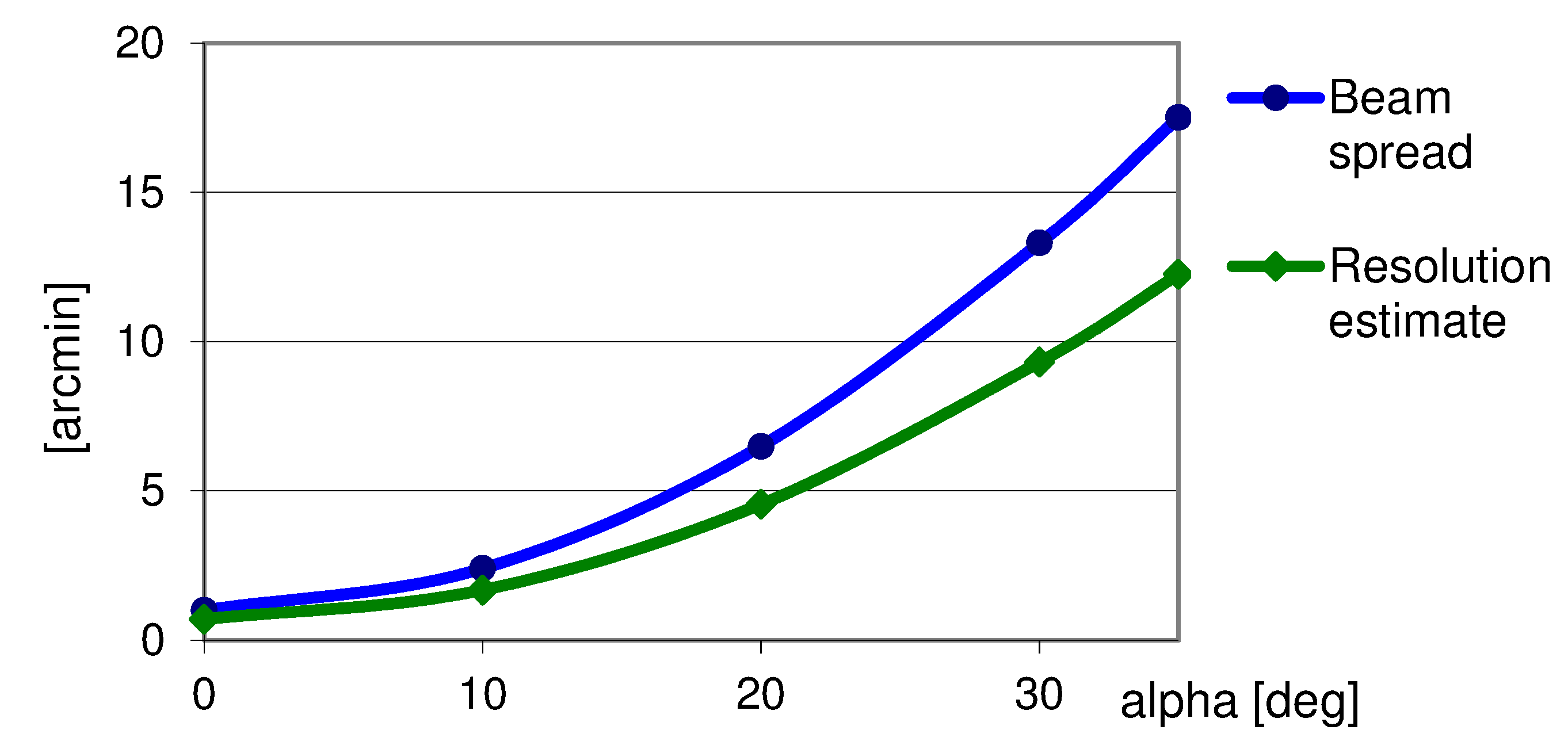
When only method 1 is used,, the beam spread is about 6 arcmin (x and y) at 20° eye rotation (edge of a 40° FOV). At 30% contrast, the usual definition for resolution figures, this implies an edge resolution of about 4 arcmin (Fig. 20), a value resembling the center resolution of some simpler AR and VR displays (there quite well accepted). One should also note that many current AR displays have only about ±10° total FOV.
Fig. 20: Circular beam spread of the planar display with dome mirror, over angle from center
(Blender simulation results), and estimated resolution figures.
Simply bending - a cylindrical display design
We may also use the same xy shape obtained, to combine the spherical coaxial principle for the horizontal with a straight shape in the vertical, resulting in a cylindrical display and a barrel shaped mirror (Fig. 21). This allows for a virtually unlimited horizontal field of view, and moreover, bending a display in only one direction is far easier than producing an entirely convex one. The astigmatism at the top and bottom is only up to 50% larger than with the planar display approach, hence the overall performance is still quite appealing (Fig. 22).
Note that the FOV here can even partly exceed that of the spherical display, because of the lesser overall curvature and the resulting larger clearance towards the physical eye periphery.
Fig. 21: Left: Cylinder display and barrel mirror (with only raw cut edges).
Right: image simulation, right eye. The highlighted area corresponds to an FOV section of 40°x70°
(24 mm equiv. camera lens), out of the huge total FOV.
Fig. 22: 40°x70° area. Note that the edge resolution will even increase when the eye is pointed there.
Considering a Hybrid Approach
Summarizing above results, the best practical solution may likely be something in between the variants analyzed:
- The spherical concept has a small eye relief and conflicts a bit with the physiognomy at its edges.. However, it also yields maximum resolution even beyond 80° FOV, where this is not necessary at all (as shown in Fig. 4).
- The flat display variant has more eye relief, but resolution degrades toward the edges. However, even a small display bending improves things a lot (as we have seen, about ¼ mm can already correct astigmatism). Moreover, more eye distance and a bigger mirror also improve edge resolution. Just as with the spherical variant however, we can’t make the mirrors arbitrary large, also because the left and right mirrors would get into each other’s way. Here it may help to make the design slightly elliptical.
- As horizontal FOV usually is more important than the vertical, choosing different horizontal and vertical curvatures, as in the cylindrical variant, could also be useful.
From all this follows that a slightly curved display with ample eye distance, combining the best of all variants discussed, should be the best practical solution.
Dynamic focus
Dynamic focus adjustment - e.g. by shifting the display back and forward (also with respect to the current viewing direction) - should be an essential part of a display glasses design. With the optical layout presented here, we may ask how big the display displacement would have to be, e.g., for simulating a 40 cm distance?
With f0 being the mirror focus length for infinity, and f1 the object focus length wanted, we may calculate the according display displacementdd = 1/(1/f0 + 1/f1) - f0
For f0 = 20 mm, f1 = 400 mm we get dd = 0.95 mm. This is easily manageable. The same displacement, by the way, would also serve to correct for 2.5 diopters short-sightedness of a user. The design hence allows for a reasonable focus adjustment range for a quick virtual object distance simulation, and also for a short- or far-sightedness of the user if prescription glasses are not integrated..
Integrating Prescription Glasses
Combining AR glasses with prescription glasses is always a challenge. While the displays can quite easily be refocused o match the user’s requirements, they cannot provide for a crisp view of the environment by themselves. Current displays often use waveguide, which are quite compact, but not as much as to fit behind existing eyeglasses, at least not behind small ones. fitting them before the eyeglasses requires special mounting assemblies, even up to helmet like ones. Similar difficulties are haunting practically any display type. For private use, where the device may be bespoke for one user. it may therefore be the best option to integrate prescription lenses directly into the display.
Prescription glasses could best be placed behind the display, as shown in Fig. 2 already, and with the designs presented here, they should best have an outer curvature similar to the display’s inner one. Which means a dedicated production process, but this should be manageable, especially also because said curvature could be quite similar for any brands of NED using this concept, so the same glass lenses could be used for various products, resulting in high volumes and lower prices. Defining a standardized mounting mechanism could further facilitate the application.
Alternative Mirror Concepts
Very obviously, the mirror in all above concepts could also be a Bragg, or holographic mirror. In this case, the effective mirror shape can deviate from the shape of its carrying glass sheet. Hence, the mirror glass shape could become less bulky, more flat and hence convenient, and also the display could have more eye relief, which would normally require a relatively big mirror glass. But in turn, a holographic mirror would be a lot thicker.
Eye Tracking
The optics discussed have the interesting feature to also deliver a picture of the user’s retina right on the displays. By integrating an array of light receptors into the display, we would get a camera recording the pattern and its position, hence the eye position. A problem here is how to get enough light into the eye to obtain a bright enough picture of the retina. Even a quite strong infrared lighting would have difficulties in daylight situations.
An alternative might be to use a blurred picture of the pupil and iris. With some image processing, even this could deliver an accurate enough pupil position.
Mask Displays
The usefulness of AR displays could be greatly enhanced by a means of shielding certain sections of the FOV against the environment, in order to display virtual objects without unwanted “transparency”. The concept and practical aspects have been discussed in [1] and [4], where it has been shown that simple masks, even close to the eye, can provide for very detailed, and surprisingly crisp object coverage. However, a convincing technology for such a “mask display” is still to be found.
The on-axis NED presented here may require a curved mask display, while waveguides would get along with a flat, likely more simple one. However, the masking works the better the more distant the mask is from the eye, and a quite promising technology could be electrochromic polymers, where considerable progress has been reported recently (see [7], just for an example). Polymers may allow for curved displays, and integrating one in the mirror would be a quite ideal solution.
Summary
WeWe have seen that high resolution near eye displays with only one mirror can be constructed if the display itself is used as a functional element in the optical design, by giving it a curved surface.
The ideal shape for display and mirror turned out to be ellipsoidal, with the center of the eye as one of the ellipsoid’s focal points.
Yet it turned out that this off-center approach suffers from the curvature changes even within the small areas contributing to the formation of single image points.
The problem was solved by changing the off-axis approach into a coaxial or on-axis one. This requires a transparent display, an unusual but possible and already available technology.
The ellipses hence became spheres, and the resolution and FOV achievable with this are virtually unlimited. But moreover, and quite surprisingly, the eyebox also turned our to be very large, in spite of the big magnification factor of the assembly.
Finally it turned out that even with a flat display, the on-axis approach yields a very large FOV, 40° of it with good resolution and a lot more on top, and also with a large eyebox.
A straightforward synthesis algorithm for the ideal mirror shape was presented and verified.
Using elements from the approaches presented, a wide variety of display and mirror shapes are conceivable, optimized for various aspects of performance and convenience, all sharing the principal advantages of the on-axis concept, i.e., high resolution and large FOV and eyebox.
Compared to the currently often favored waveguide displays, the form factor of this approach is bigger, but the functional elements can be made arbitrarily thin and therefore light, the FOV is a lot larger and the eyebox also is very large. This allows to use a simple eyeglasses frame instead of the usual helmet-like constructions. Eye relief is smaller than with most waveguide devices, but wearing them together with prescription glasses is difficult with both approaches, anyway. Yet, prescription lenses can easily be integrated into the configuration.
The approaches presented have been evaluated by 3D raytracing with freely available open source software (Blender), which proved to be fully able for the simulation of optical resolution as well as physiological and aesthetic design aspects. This allows for a more comprehensive evaluation than with classical optics design software.
The Blender model used for the simulations and a set of video tutorials can be obtained (for non-profit use only) from the website of [4] (http://www.displaysbook.info, "materials" page).
References
[1] The end of Hardware; Rolf R. Hainich, Booksurge 2006, 3rd Ed. 2009. ISBN 9781439236024
[2] O. Cakmakci, S. Vo, S. Vogl, R. Spindelbalker, A. Ferscha, J. P. Rolland: Optical Free-Form Surfaces in Off-Axis Head-Worn Display Design. 7th IEEE and ACM International Symposium on Mixed and Augmented reality, ISMAR, Cambridge, 2008.
[3] Jianming Yang, Weiqi Liu, Weizhen Lv, Daliang Zhang, Fei He, Zhonglun Wei, Yusi Kang: Method of achieving a wide field-of-view head-mounted display with small distortion. OPTICS LETTERS 203 / Vol. 38, No. 12 / 2013
[4] Displays- Fundamentals and Applications, Rolf R. Hainich and Oliver Bimber, Taylor&Francis, 2nd edition 2016. ISBN: 9780367658175
[5] EP0580261A1, Combined display and viewing system; Masakazu Kawada 1993
[6] US6407724B2, Method of and Apparatus for Viewing an Image; Waldern et al. 2002
[7] Xu, T. et al. High-contrast and fast electrochromic switching enabled by plasmonics. Nat. Commun. 7:10479 doi: 10.1038/ncomms10479 (2016).
[8] Rolf R. Hainich: Near Eye Displays - a Look into the Christmas Ball. Keynote Lecture. 7th IEEE and ACM International Symposium on Mixed and Augmented reality, ISMAR, Cambridge, 2008. https://dl.acm.org/doi/10.1109/ISMAR.2008.4637310
1All rights preserved. Patents pending or granted, e.g.: DE102014013320B4; GB2537193B, US11867903B2.
Resources download
You are welcome to download the complete Blender model with several display/mirror designs included, additional details on the calculus used, as well as a complete set of tutorial videos.
Please enter your name and a valid e-mail address into the form fields below and click on Submit.
We will immediately e-mail you a download link for the resources (zip file, approx. 120 MB).
If you think this material is of any value to you, please consider making a donation to Sea Shepherd.
home news


Copyright © 2012-2024 Rolf R. Hainich; all materials on this website are copyrighted.
Disclaimer: All proprietary names and product names mentioned are trademarks or registered trademarks of their respective owners. We do not imply that any of the technologies or ideas described or mentioned herein are free of patent or other rights of ourselves or others. We do also not take any responsibility or guarantee for the correctness or legal status of any information in this book or this website or any documents or links mentioned herein and do not encourage or recommend any use of it. You may use the information presented herein at your own risk and responsibility only. To the best of our knowledge and belief no trademark or copyright infringement exists in these materials. In the fiction part of the book, the sketches, and anything printed in special typefaces, names, companies, cities, and countries are used fictitiously for the purpose of illustrating examples, and any resemblance to actual persons, living or dead, organizations, business establishments, events, or locales is entirely coincidental. If you have any questions or objections, please contact us immediately. "We" in all above terms comprises the publisher as well as the author. If you intend to use any of the ideas mentioned in the book or this website, please do your own research and patent research and contact the author.