Augmented Reality is more than Virtual Reality
Laser scanners
Laser scanners are usually built with tiny agitated deflection mirrors. These are usually manufactured in chip technology (micro electro mechanical systems, MEMS), etching the entire device including frames and hinges (h) from a single substrate:
The mirror is agitated by electrostatic or magnetic force. Unwanted resonances and parametric effects have to be addressed by proper driver design and damping. Some recent information you can find at Microvision or FhG-IPMS.
Problem: these mirrors cannot be really microscopic even for eye projectors, as concentrating a laser beam sufficiently requires a minimum source size, 0.5 mm for an angular resolution of 4 arcmin and 2mm for 1 arcmin (which is the maximum angular resolution of the human eye). This works analog to the equation for the minimum lens aperture for a certain focus size. For a high resolution display we therefore need a mirror diameter of 1mm or more, and such a "large" mirror can hardly support the deflection frequencies of up to 100 kHz necessary in this case.
Using multiple mirrors to generate coarser wide angle pictures with crisper inlays at the actual direction of view could resolve for this.
The following picture has a crisp part of 1/3 size in the middle, the outer part is 4 times less crisp. (This example is made for a typical computer monitor and presented here on this website only). Just look at the guy in the center without ever moving your eyes. The fuzziness of the outside will then hardly be visible any more.
For a wide angle image, 3 or even 4 staged inlay levels may be used. The inlay must instantly follow the user's eye movements, so we also need eye trackers of course.
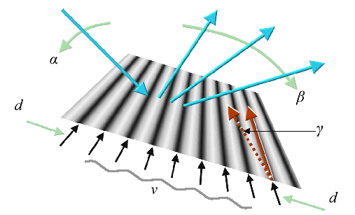
A single laser beam could be split to light 3 or 4 adjacent mirrors at once, and such an assembly may be manufactured as a single tiny MEMS structure. The mirror for the center part may have to be up to 1mm "large" and needs to scan with a speed of several kHz, but only for a very small angle (plus slow motion at full angle to follow eye movements). The mirror for the outer part could be much smaller, 0.02 mm for example as it only needs to write much fuzzier pixels, but it needs to support a higher speed (the eye is more flicker sensitive at the border) and the full image angle. With such a small mirror though, this is possible. Multiple resolution inlays could therefore resolve the size/speed conundrum with mirror scanners.Holographic reflection patterns produced by really fast switching displays could be an alternative. A holographic pattern of straight equidistant lines, a so called holographic grating, can also be used as a mirror, as the light reflected from different lines only adds up for certain angles (constructive interference).
The so called grating equation (a textbook item, also explained in the book) would reveal that for infalling angles
of about 50...60 degrees, we could generate departing angles between about 10 and 80 degrees while being able to simply trap any unwanted 'conjugated beams' or 'modes'.
Feeding sine wave patterns v of different wavelengths into a display chip, we could vary the deflection angle
in a wide range and at almost any speed. Changing the line angle y as well, we could deflect in two axes at once, but this is difficult as well as not strictly necessary, as we could as well tilt the entire (tiny) deflection chip for the slow axis. A disadvantage of the holographic mirror approach is that the reflection effectiveness is way below 100%.
During head movements, images have to be repositioned dynamically in order to appear steady. With any sequentially scanning display, like CRT tubes and lasers, each image part has to be calculated separately, for the head position at its proper display time. With laser scanners, especially holographic ones, even beam deflection could be modified to achieve steadiness. Due to system delays, user's head movements have to be 'predicted' from speed and acceleration at a given time, which is rather precise due to the relatively big inertia of the head. These last remarks should be basics, since VR systems have been around for so long now, but from publications one sometimes gets the impression that it's not really so clear at all.
Coaxial moving mirror chip concept (real size here: )
Let's have a closer look at the multi-mirror concept from the book. The best option for this are concentric mirrors, as they work with a just minimally adapted beam and no other optical tricks.
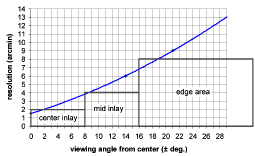
An example: with 3 mirrors producing staged inlays of 1:2:4 in size, each mirror just writing about VGA resolution to get a total resolution way beyond HDTV. At a resolution around 2 arcmin. (a very crisp picture impression already, like an excellent PC screen), the total field of view served could be more than 60x90 degrees (most people's ordinary glasses have less).
The outer mirrors would have to be rings of course, but this is an advantage: the inner parts of them would only contribute more blur, as we have learned from the lens metaphor. An outer mirror ring only 1mm in diameter (look at the picture legend above, to see how tiny this is) could draw the innermost picture inlay, with its small viewing angle and hence very small excitations.
The eye is less flicker sensitive at its center of view, so this mirror could be relatively slow. We could also use interlacing (running lines can't happen because the picture follows eye movements). In consequence, the deflection rate necessary is no more than 10 kHz.
The next ring would be about 0.5 mm 'large', and the center mirror about 0.25 mm, delivering the larger focus spot and better agility needed for the outer picture areas. How do we follow eye movements with the small inlay mirror excitations described? Simply tilt the entire chip, by the same micro motors doing the eye and fit adaptation anyway. The tiny center mirrors drawing the outer images, could probably compensate against this sufficiently within their own deflection range.
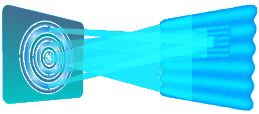
Operation scheme of a multiple inlay scanner Resolution of staged inlays vs. a typical single eye resolution curve Existing products are not yet this advanced, but development goes on. Have a look at some new Results from FhG-IPMS for example.
home more notes order
Copyright © 2006-2011 Rolf R. Hainich; all materials on this website are copyrighted.
Disclaimer: All proprietary names and product names mentioned are trademarks or registered trademarks of their respective owners. We do not imply that any of the technologies or ideas described or mentioned herein are free of patent or other rights of ourselves or others. We do also not take any responsibility or guarantee for the correctness or legal status of any information in this book or this website or any documents or links mentioned herein and do not encourage or recommend any use of it. You may use the information presented herein at your own risk and responsibility only. To the best of our knowledge and belief no trademark or copyright infringement exists in these materials. In the fiction part of the book, the sketches, and anything printed in special typefaces, names, companies, cities, and countries are used fictitiously for the purpose of illustrating examples, and any resemblance to actual persons, living or dead, organizations, business establishments, events, or locales is entirely coincidental. If you have any questions or objections, please contact us immediately. "We" in all above terms comprises the publisher as well as the author. If you intend to use any of the ideas mentioned in the book or this website, please do your own research and patent research and contact the author.


