Augmented Reality is more than Virtual Reality
New Ideas for Displays
Intelligent planar micro displays and their application
Recent progress in micro displays enables new concepts for advanced display glasses. What we are presenting here is an entirely new approach exploiting these possibilities .
For displays based on CMOS chip technology (OLED-on-CMOS in particular), several interesting capabilities are known already:
Another possible advantage has been pointed out very little so far, if at all:
- Pixel sizes can be extremely small. This allows the production of very small display chips of extremely high resolution.
- Light sensitive pixels can be inserted between the luminating ones, allowing for the integration of a camera function into the display die, enabling new approaches like retina tracking.
- Infrared pixels can be integrated, offering illumination for eye or retina tracking.
CMOS structures can be a lot smaller than even the finest useful display pixel structures, allowing for the integration of additional functionality into the chip. But before we return to this idea in detail, let us first have a look at certain application requirements, especially with augmented reality.
A crucial problem with head-mounted displays is the performance with fast head motion (especially: turning the head), with displayed virtual objects registered to the environment.
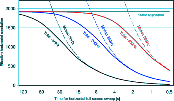
Consider a user turning his head, while keeping his eyes directed to a virtual object. For the display glasses, this means shifting the entire image of the virtual object across the display chip area. Even at high frame rates, this may give raise to jitter and smearing, and the effect becomes more important the higher the display resolution is. The following illustration shows how severe this gets for HD displays in video or TV applications:
Resolution vs. motion speed, for full HD displaysIncreasing the frame rate is not a good answer to this, as for a decent level of perfection we would need way above 200 Hz. Another usual measure - Flashing the single frames - works as long as the viewer can/does follow motion with his eyes. Only in this case, the single flashed images will add up at the same spot on the retina, resulting in a steady impression. Fortunately, flashing may work to eliminate smear effects in simple head-turning-while-fixating-an-object situations in augmented reality.
Nevertheless, a problem remaining in AR applications is the Display's inherent delay time - the frame duration. Although the detection of head motion by inertia sensors is very fast, this delay time makes is necessary to 'predict' the correct position one frame ahead. The inherent inertia of a human head allows motion anticipation algorithms to work relatively well. Depending on the actual application, this may suffice or not. Again, even small remaining errors may become big enough to be disturbing, with increasing display resolution.
Scanning displays (laser scanners) may allow for an instantaneous reaction to quick head turns, by directly changing direction and speed of the deflection element, even right within a scan line. Yet, scanners have the speed/resolution dilemma (higher resolution needs larger scanning mirrors and higher scan speed at the same time) as well as possible problems with small exit pupils, so as of now, no perfect display of this kind is in sight.
Planar displays can be very light. Theoretically, chips can be extremely thin, so this enables constructions not heavier than a laser scanning device. Moreover large exit pupils, large viewing angles and high resolution can be achieved quite easily, and with also very light optics (thin plastic shells with mirror coatings). Hence, if we could add capabilities for fast motion reactions, this would render them quite ideal.
We will now show a possible way to include the (also still theoretical) fast reaction capability of scanning displays into planar displays. We will also show a possibility to spread low resolution images over a larger display area for a creation of large peripheral viewing angles with very little computing requirements.
Frame shifting
Pixel wise frame shifting for a smooth motion impression
With a CMOS based display, we could think of adding circuits between adjacent pixels, allowing for a direct electric charge transfer between neighboring pixels, which would result in shifting the image within the display array, in single pixel steps. The underlying principle of this idea is decades old: charge coupled devices (CCD) have been implemented with the earliest CMOS logic chip families already, and CCD camera chips using it are about as ancient. Only for displays, this seems to be quite a new idea.
With the CCD circuitry, simple trigger pulses could initiate a move of the entire image by one pixel width each, in up, down, left or right direction. Multiple operations of this kind, correctly timed, could move the image in about any direction and at any speed.A simple circuit can control the shifting for the entire display. For a smooth motion impression, we would want to distribute the shifting operations properly over time. This can be achieved using a shift controller with several extra bits, encoding fractions of a pixel size:
Think of two separate counters for the lateral and vertical directions (x and y), each running at a clock rate proportional to the desired motion speed in that direction. The counters should have several extra bits at the low end, and they should increment many times more often than the actual shifting operations. If we initiate an actual pixel shift only when a certain higher bit of the counter changes, we get an average shift speed at the accuracy of the least significant bit implemented.If pixel shifts in x and y occur simultaneously, we may add a short delay for one of them, to avoid possible conflicts between charges arriving at a pixel from x and y directions simultaneously. The very fast sequence of x and y shift resulting would almost perfectly simulate a diagonal shift.
Such a time-dithered pixel-by-pixel motion of the entire image, should be perceived as rather smooth , especially if the pixel sizes involved are at the edge of possible eye resolution (which should be the case for HD displays).
While writing or refreshing a full image at usual video frame rates takes 17...20 ms, a pixel shift could be carried out in even less than a microsecond, and many small shifting steps would provide a continuous motion, until the next frame refresh takes over exactly from the resulting end position.
The complete design should include a second storage layer where the next frame can be written to in background, while the displayed (foreground) image is being shifted. The complete background image could then be uploaded to the foreground, also by a quick CCD operation.
We should note that an image filling the entire display area will leave empty edge pixels behind at one side. This can be compensated for by various techniques already known from image stabilization or resizing, but the easiest way would be not to display pixels close to the edges of the chip, so these initially invisible edge pixels would automatically fill the visible edge area during shifting operations.
For virtual display (virtual reality) objects, this entire issue is of no importance as long as they are occupying only a fraction of the display chip area.Frame rotation or zoom operations on the displayed image content would also be possible to carry out by pixel shifting, but would involve far more complex shifting schemes, that would have to be different for different parts of the image. Such operations could be of advantage for large, spatial displays (e.g., exploiting the motion vectors already available in current video compression formats), but for augmented reality display glasses, it would probably not be very useful, as tilting or forth/back motions of the human head occur at far slower paces than just turning (which requires the shift motion compensation alone).
In conclusion, a quite simple addition to the functionality of a display chip with integrated circuitry would offer great advantages for motion compensation and enable a rock solid registration of virtual objects in augmented reality applications.
Variable resolution rendering
The rendering effort for near-eye displays can be greatly reduced by exploiting the eye's lower resolution outside the center of view. The human eye has a center resolution of approx. one arcmin (1/600). For a decently large field of view, e.g., 900x600 per eye (a center overlap of 400…500 can be considered sufficient), displays of 5400x3600 pixels each would be 'nice to have'.
Building an OLED-on-CMOS display chip of such resolution is not a real problem, but rendering or transmit-ting images with such a spatial - and also a good temporal - resolution certainly is.
The possibility to render only necessary data, i.e., providing low resolution wide angle images with high resolution inlays, dynamically positioned using an eye tracker, offers advantages both in terms of computing power and transmission bandwidth.
The mentioned 3600x5400 resolution, e.g., could be realized by an outer frame with inlays of ½ and ¼ size, each consisting of 1350x900pixels. The reduction of the total number of pixels to be rendered is 10/64 of the high resolution full frame.
Simply rendering at a lower resolution, however, would be of no advantage: the rendering processor would have to calculate less actual image pixels, but would then have to fill the pixels between them and smoothen the result. This would save about nothing. If we could accomplish the pixel filling inside the display chip itself, however, and the smoothing as well, we would gain a real advantage.
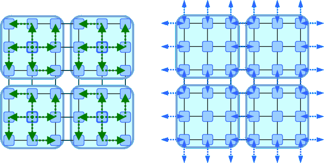
Step 1: block filling (here: in two steps) Step 2: deblocking Consider a random addressable CMOS display chip. Consider writing to single pixels, e.g., every 2nd, 3rd, 4th of the actual display pixels. Charge transfer functions implemented within the display chip could then be used to fill several adjacent pixels (e.g., a block of four, nine or sixteen display pixels) with that information (note that in this case it has to duplicate charges rather than just shifting them).
Subsequently, an appropriate chip circuitry could provide for a smoothing of the resulting coarse image raster, by averaging pixels (charges) at block edges with adjacent ones from neighboring blocks.
In the above illustration, we have shown a two-step duplication operation designed to avoid target pixel conflicts. An averaging of incoming charges from two or more directions is also conceivable, depending on the circuit design. This would especially be useful for the second step, the deblocking. It could also be used to avoid lateral half-pixel offsets for schemes with even numbered reductions (very 2nd, 4th etc… pixel), if that matters.
These ideas have first been presented to a larger audience at the BiTS2012 conference.
Further considerations
If a linear distortions by the optics are electronically compensated by the display image, the motion vectors in the display matrix will not be perceived entirely parallel by the user. This may perhaps result in some remaining motion effects in the peripheral field of view. For a dedicated display design in conjunction with display glasses optics, it may therefore be advisable to have a non-linear arrangement of the display matrix itself, already providing the right geometric compensation for the optics given. This can certainly be accomplished, only the chip design software may not be ready for it. With this, all motion vectors in the display array will again appear parallel for the observer.
home news order
Copyright © 2012 Rolf R. Hainich; all materials on this website are copyrighted.
Disclaimer: All proprietary names and product names mentioned are trademarks or registered trademarks of their respective owners. We do not imply that any of the technologies or ideas described or mentioned herein are free of patent or other rights of ourselves or others. We do also not take any responsibility or guarantee for the correctness or legal status of any information in this book or this website or any documents or links mentioned herein and do not encourage or recommend any use of it. You may use the information presented herein at your own risk and responsibility only. To the best of our knowledge and belief no trademark or copyright infringement exists in these materials. In the fiction part of the book, the sketches, and anything printed in special typefaces, names, companies, cities, and countries are used fictitiously for the purpose of illustrating examples, and any resemblance to actual persons, living or dead, organizations, business establishments, events, or locales is entirely coincidental. If you have any questions or objections, please contact us immediately. "We" in all above terms comprises the publisher as well as the author. If you intend to use any of the ideas mentioned in the book or this website, please do your own research and patent research and contact the author.


